ESP8266如何使用UART串口通讯
开始使用
本来根据demo设置了串口通讯,但总发现无法正确接收,故找了一些方法并尝试之,最后发现,将LOG打印调整且UART管脚做调换才最终实现正常收发,看别人说不用将管脚交换也行,只是自己这边没成功!
简介
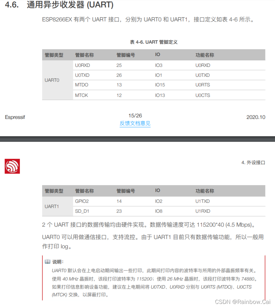
ESP8266 有两个UART。UART0有TX、RX作为 系统的打印信息输出接口 和 数据收发口,而UART1只有TX,作为 打印信息输出接口(调试用)。
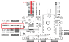
总体介绍
ESP8266 有 2 组 UART 口,分别为 UART0 和 UART1。
默认 UART0 主要是用做固件下载和程序日志输出
而 UART1 因为只支持 TX,所以一般在需要 UART 用于通讯时,建议用 UART1 来输出日志信息。参见《ESP8266 技术规格书》说明。
UART0接收
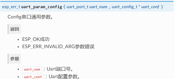
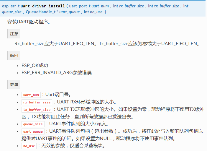
加入代码
1 | /********************************************************************* |
使用流程
①串口初始化UART_Init(); // 设置串口0
②串口中断处理uartEventTask(void *pvParameters); // 串口事件处理函数
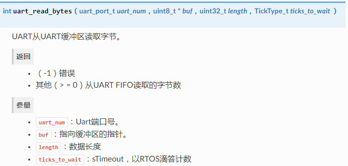
主要修改下面这个函数在 case UART_DATA 中使用 uart_read_bytes 读出数据然后进行处理
UART0发送
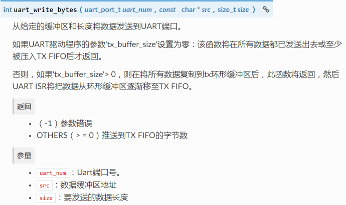
相关函数
使用流程
①串口初始化UART_Init(); // 设置串口0
②串口发送数据uart_write_bytes(uart_port_t uart_num, const char *src, size_t size); // UART0 发送数据函数
UART1打印日志
在 ESP8266_RTOS_SDK-3.2 中任何例程中输入make menuconfig
选择 Component config

选择 Common ESP-related
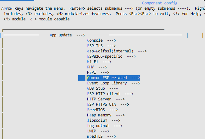
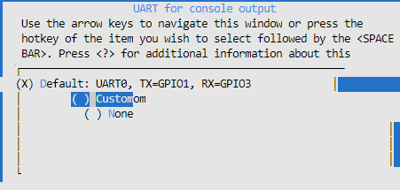
选择 UART for console output
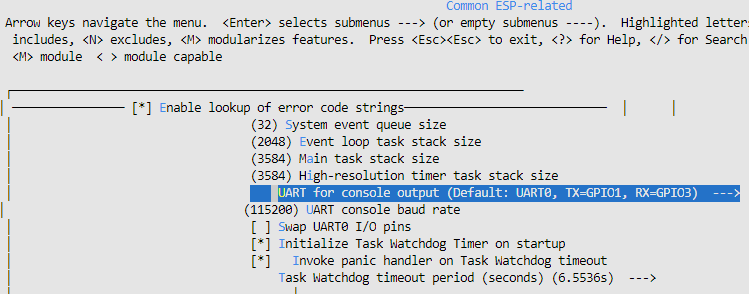
从默认串口0改为 Customon
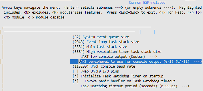
选择 UART peripheral to use for console output 改为 UART1 输出
基本使用说明
ESP8266 下载串口(UART)
- ESP8266 只能通过 UART0(GPIO1 和 GPIO3)来下载固件,下载管脚不可更改。
- 请参见“ESP8266 固件烧录需满足的硬件环境” 说明。
2 ESP8266 日志输出串口(UART)
- ESP8266 软件中默认使用的是 UART0 来输出程序日志。
- ESP8266 芯片上电启动的 一级 bootloader 的输出日志的串口波特率为
74880 bps(此波特率不可更改),使用的是外部26MHz的芯片启振晶振。请参考 “ESP8266_RTOS_SDK/components/bootloader_support/src/bootloader_init.c” 说明。 - ESP8266 的程序运行输出日志默认使用的串口波特率为
74480 bps,使用的是 SPI Speed 的40MHz的晶振,与 CPU 主频有关。可在 menuconfig 中进行修改,如下:menuconfig —> Component config —> Common ESP-related —> UART console baud rate
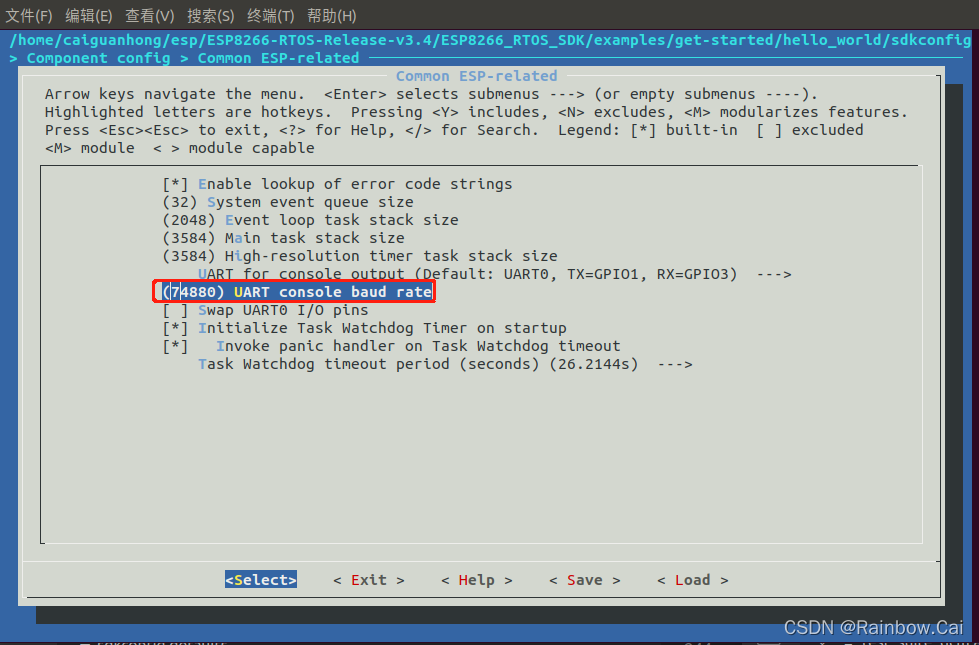
默认设置范围是 1200 bps ~ 4M bps ,如下:

目前屏蔽 UART0 的日志输出方式有两种:
① 通过调用相关 API 来屏蔽 UART0 的日志输出:
- 只屏蔽应用层的打印,调用 UART_SetPrintPort(UART1) 或者 system_uart_swap() 函数就可以了。
- 屏蔽掉所有信息(从 boot 启动阶段就开始屏蔽掉),调用system_uart_swap() 函数,同时要在硬件上做修改,具体的原理可参考《ESP8266 技术参考手册》
page 88~89。注意:system_uart_swap()函数屏蔽的是通过 GPIO13 和 GPIO15 来作为串口输出的 log 。
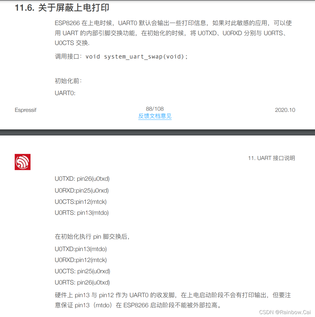
② 通过 menuconfig 配置端可关闭的日志如下:
关闭 Bootloader 日志:
menuconfig -> bootloader config –> bootloader log verbosity 选定为 No output 。
关闭程序运行日志:
menuconfig -> Component config –> log output –> Default log verbosity 选定为 No output 。
关闭其他日志输出:
menuconfig -> Component Config ->Common ESP-related -> Channel for console output -> None 。
更换程序日志输出串口为 UART1:
menuconfig -> Component Config ->Common ESP-related -> Channel for console output -> Custom UART -> UART peripheral to use for console output(0-1) -> UART1。
3 ESP8266 串口(UART)通信(这里解决了接收发送问题)
参考资料:
《ESP8266 技术参考手册》 中的 “
UART 接⼝说明” 章节:描述 UART 的功能、硬件资源、参数配置、配置中断、中断处理函数示例流程、屏蔽上电打印。ESP8266 在上电时候,UART0 默认会输出⼀些打印信息,如果对此敏感的应⽤,可以使用 UART 的内部引脚交换功能,在初始化的时候,将 U0TXD、U0RXD 分别与 U
0RTS(GPIO15)、 U0CTS(GPIO13)交换来与 MCU 进行 UART 通信。可参考《ESP8266 技术参考手册》 `page 88~89通过 UART0 的 U0RTS(GPIO15)、 U0CTS(GPIO13) 管脚交换来实现 ESP8266 与其他芯片的 UART 通信时,交换管脚 MTDO(GPIO15)作为 TXD 、MTCK(GPIO13)作为 RXD 。
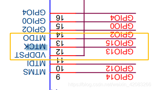
- ESP8266 通过 UART0 的 U0RTS(GPIO15)、 U0CTS(GPIO13) 管脚交换与另一个芯片的 UART 通讯时,可调用 uart_enable_swap() API 来实现。参考 “ESP8266_RTOS_SDK/components/esp8266/driver/uart.c”
1 | esp_err_t uart_enable_swap(void) |
- ESP8266 的 UART0 例程参考:ESP8266_RTOS_SDK/examples/peripherals
包含如下测试例程:
- 通过 UART 接口将接收到的数据回传给对端设备:peripherals/uart_echo
- 通过 UART 检测接收到的不同的指令来触发对应的事件:peripherals/uart_events
- 在 UART 接口上使用同步 I/O 多路复用。UART 可作为 Monitor 打印日志,又可读写数据:peripherals/uart_select
【ESP8266 UART 通信常见应用问题】
ESP8266 的串⼝波特率范围是多大?
ESP8266 的串⼝波特率范围从 300 到 115200*40 都可以⽀持。参见 《ESP8266 技术参考手册》中的“ 11.3.1. 波特率 ”章节说明。ESP8266 UART 的硬件 FIFO 是多大?
ESP8266 的 UART0 和 UART1 各有⼀个⻓度为128 Bytes的硬件 FIFO,读写 FIFO 都在同⼀个地址操作。参见 《ESP8266 技术参考手册》中的“ 11.2. 硬件资源 ”章节说明。
4 ESP8266 AT 传输串口
【不推荐】ESP8266 V2.0.0.0 以下版本的 AT 固件默认使用的 AT 串口是 UART0 (即 GPIO1 和 GPIO3),流控引脚是 GPIO13 和 GPIO15 。可参见 《ESP8266 Datasheet》
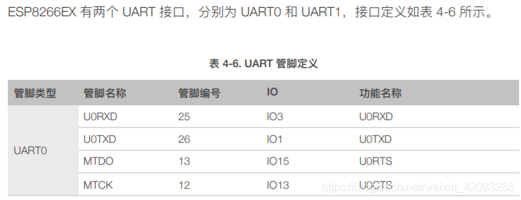
【推荐】ESP8266 V2.0.0.0 及以上版本的 AT 固件默认使用的 AT 指令传输串口是 GPIO15 和 GPIO13,流控引脚是 GPIO3 和 GPIO1 。可参见 ESP-AT 出厂配置参数。ESP8266 V2.0.0.0 及以上版本的 AT 固件默认的串口波特率分别为:
1. UART0 打印芯片上电启动日志,波特率为 74880 bps,使用的是 26 MHz 的芯片启振晶振;
2. GPIO15(TXD) 和 GPIO13(RXD) 为 AT 传输串口,默认波特率为 115200 bps,使用的是 SPI Speed 的 40 MHz 的晶振,与 CPU 主频有关。
- ESP8266 的 AT 指令传输串口和波特率可通过自行编译 ESP-AT 固件来修改 ESP-AT 出厂配置参数,可参考“Ubuntu18.04 上 ESP8266(ESP-WROOM-02) 的 esp-at release_v2.2.0.0 编译环境搭建” 说明。
5 ESP8266 串口(UART) 性能
ESP8266 的波特率硬件是可以支持到 4.5 Mbps, 但是不建议软件使用这么高的波特率, 原因有两点:
- 接收模式下,波特率太高,大量数据传输软件可能无法及时取走硬件 FIFO 中的数据从而导致数据丢失。ESP8266 的硬件
UART FIFO是128 Bytes,ESP8266 的 UART 说明你可以阅读 《ESP8266 技术参考手册》 ,建议波特率不要超过2 Mbps。如果系统有很多中断或有使用 Wi-Fi,该值需要低一点,以证数据不会丢失。 - 有些串口芯片无法支持这么高的波特率,或者 ESP8266 波特率误差超过串口芯片允许的误差范围,因为当波特率不能被 ESP8266 串口模块时钟(
80 MHz)整除的时候,就存在误差。
当 UART 波特率过高导致接收数据丢失时,我们的建议:
- 增加 UART 硬件流控
- 降低 UART 波特率
相关链接(侵删)
- ESP8266学习笔记(21)——UART串口使用(RTOS SDK)
- ESP8266 的串口(UART)使用
- 【常用模块】ESP8266 WIFI串口通信模块使用详解(实例:附STM32详细代码)
- ESP8266_RTOS_SDK
- ESP8266串口的使用
欢迎到公众号来唠嗑:


